false|||
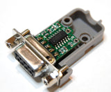
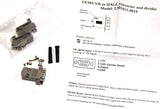
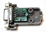
An (LM1815) VR to HALL interface and a (HC4024) counter chip in a small DSUB9 connector housing.
- Requires 5V supply (from the assembled v3 controller EC36/28 pin, or other source, only appr. 10mA needed)
- The LM1815 (adaptive hysteresys threshold VR interface chip, the adaptive input mode can be configured in 3 modes with simple solder-blob) output is available, normally low level, outputs 1 short (less than 100 usec) high-pulse at the negative-going zero crossing edge of the input pin. Useful for using VR (crankpos, campos or wheelspeed) sensors when the ECU (or other device) is equipped with HALL signal input.
- The output of LM1815 goes to 4024 counter / frequency divider. This divided output (divby8) is useful for ABS wheels that have more than 10 pulses per wheel rotation. The reset input signal of the 4024 is available on the DSUB9 pinout (can be used as prohibit signal to reset the counter, keep output low). Normally the divided output is only useful for wheelspeed signal, not for crank or cam position. However for bench-testing PC soundcard => VR to HALL => divider => v3 with HALL type input configured to "coil-type" none-missing tooth trigger can be useful to enable testing at lower RPM where the given soundcard would be otherwise problematic, noisy (because of internal high-pass filter).
All outputs are 0/5V, like "HALL" or optical sensor signals. Divider options: (divby4 and divby8 are wired via PCB trace to DSUB9 pin)
- divby8 selectable with solderblob (default)
- divby4 selectable with solderblob
- divby2 only available on the 4024 chip, not selectable with solderblob (not recommended)
- To get HALL signal without dividing, one needs to solder a wire from LM1815pin12 (solder to the resistor, the trace goes to the 4024 divider chip) to the DSUB9. Because of the short pulses, the "without divider" signal is NOT suitable FOR WHEELSPEED. Only useful for primary or secondary trigger (when one wants to use VR sensor with an ECU - v3 or possibly other type ordered with HALL input),


